The service life of slewing bearings is not only determined by material and heat treatment process; standardized installation procedure is the core factor affecting long-term failure rate. Statistics from after-sales service show that over 70% of premature failures including abnormal wear, gear fracture and slewing jamming stem from non-standard installation. A single error in any of the 6 core installation steps will directly reduce the bearing service life by more than 30%. This article fully breaks down the 6 standard procedures from pre-installation inspection to final calibration, clarifying operating standards, forbidden operations and acceptance criteria for each step to help maintenance and assembly staff eliminate hidden installation risks.
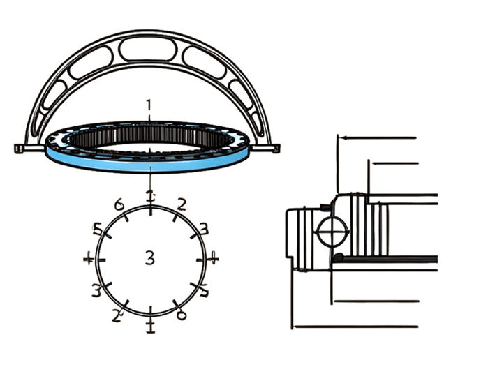
Step 1: Comprehensive Pre-installation Inspection
Before hoisting, double inspection of the bearing and mounting base must be completed as the first barrier against inherent failures.
- Bearing inspection: Check raceway and tooth surface for dents, scratches, rust and insufficient grease; confirm intact sealing rings; verify model, module and mounting hole parameters match the equipment.
- Base flatness test: Use spirit level and feeler gauge to measure flatness of upper and lower mounting flanges, with tolerance ≤0.05mm/m. No welding slag, protrusions or deformation are allowed on flange surface, which would cause eccentric load on the bearing.
- Fastener verification: Bolts and washers shall comply with original grade standard; evenly coat high-temperature anti-seize grease on bolt threads.
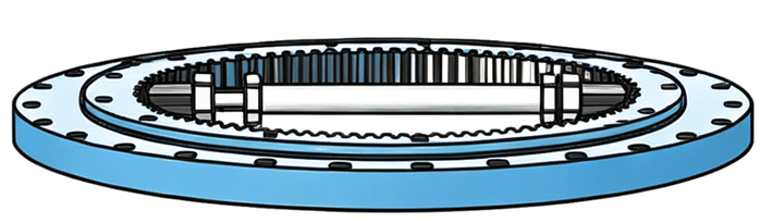
Step 2: Standard Hoisting & Positioning
Slewing bearings are thin-walled and prone to permanent raceway deformation from improper hoisting.
- Special lifting tools are mandatory with symmetric lifting points. Do not bind steel wire ropes directly around gear rings or raceways; single-point lifting and inclined dragging are strictly forbidden.
- Keep the bearing horizontal during the whole lifting process, slowly move it above the base and lower vertically to fit the flange; impact or collision against mounting surface is prohibited.
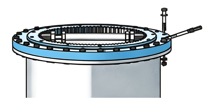
Step 3: Precise Centering & Positioning
Centering deviation is the main cause of eccentric wear and unilateral gear knocking in later operation.
Fully fit the bearing positioning spigot with the base spigot to reserve uniform circumferential clearance. Use a feeler gauge to check the fitting gap all around the bearing and flange, with gap difference controlled within 0.03mm. If partial excessive gap occurs, re-level the base instead of forcing compression for correction.
Step 4: Staged Diagonal Bolt Tightening
Most bearing fracture failures result from one-time full bolt tightening or unilateral fastening.
Adopt the 3-stage diagonal tightening method:
- 1st pass: Pre-tighten all bolts to 30% rated torque only for positioning fitting;
- 2nd pass: Tighten cross-diagonally to 70% rated torque for even stress distribution;
- 3rd pass: Repeat diagonal cycle to reach 100% rated torque to eliminate stress concentration.
Circumferential sequential tightening and one-time full torque are forbidden to prevent flange deformation under uneven load.
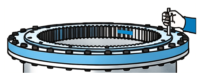
Step 5: Gear Meshing Clearance Inspection & Calibration
Abnormal gear clearance leads to abnormal noise, gear fracture and reduced transmission efficiency.
Mesh the slewing motor drive gear with the bearing gear ring, measure backlash at 4 evenly distributed positions around the gear ring. Standard backlash ranges from 0.1 to 0.3 times the module, with maximum gap difference ≤0.05mm among four points. Too small clearance causes overheating and gear burning, while excessive clearance brings impact noise; adjust shims to calibrate precisely.
Step 6: Initial Grease Filling & Final Precision Recheck
Final lubrication and recheck are critical for smooth initial operation.
- Inject special grease matching working conditions into raceway and gear cavity via multiple grease nipples until old grease and impurities overflow from the opposite side, ensuring no dry friction area inside raceway.
- Manually rotate the bearing slowly for 2~3 full circles. If no jamming or abnormal resistance appears, recheck bolt torque, gear backlash and fitting gap.
- Conduct no-load low-speed test run for 30 minutes; installation is qualified if no jitter, abnormal noise or grease leakage occurs.
7. Summary of Common Installation Mistakes
Many assemblers simplify procedures and skip inspection steps to save working hours, yet drastically shorten bearing service life. Skipping staged diagonal tightening alone leads to loose bolts under long-term load and unbalanced raceway stress, causing severe eccentric wear within 3-6 months. Direct assembly without gear clearance calibration easily results in gear root fracture under crushing conditions.
The 6-step procedure is interconnected with no dispensable links. Whether installing new bearings or reinstalling repaired ones, standardized procedures and full-process inspection must be strictly followed to achieve the designed service life of slewing bearings and reduce long-term equipment operation and maintenance costs.
About BRISK: 13 years OEM-compatible slewing bearings & construction machinery parts. Visit https://www.briskslewing.com | Contact: [email protected]