Gear backlash is the core parameter for meshing between slewing bearings and drive motor gears, directly affecting transmission stability, tooth surface wear rate and equipment operating noise. Insufficient backlash causes gear meshing jamming, overheating and scuffing, accelerating tooth surface wear; excessive backlash leads to impact noise and concentrated tooth root stress, which easily triggers gear fracture under heavy crushing loads. Many assemblers adjust backlash only by experience, ignoring standard values corresponding to module and tonnage as well as the runout high-point rule, resulting in premature bearing failure. This article compiles standard backlash values for different modules and tonnages, explains the high-point adjustment method and full-circle recheck requirements, providing a standardized operation basis for on-site assembly and maintenance.
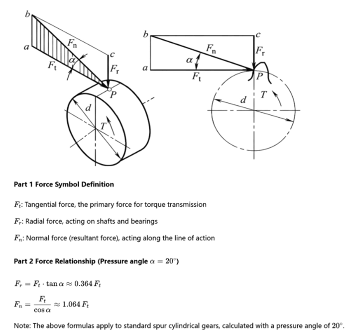
1. Standard Backlash Values Corresponding to Module & Tonnage
The baseline value of gear backlash is determined by gear module, and shall be fine-tuned according to machine tonnage and working conditions. The following are recommended normal backlash ranges under normal temperature general conditions, covering full tonnage from mini excavators to mining excavators:
Typical Application
- Mini excavators, light rotary platforms;
- Earthwork excavators, general construction equipment;
- Heavy excavators, port lifting equipment;
- Open-pit mining excavators, super-heavy slewing mechanisms.
2. Runout High-Point Adjustment Method (Core Principle)
Affected by machining accuracy and installation deformation, the slewing bearing gear ring has radial runout along the full circle, resulting in uneven backlash at different positions: backlash is smallest at the radial runout high point and largest at the low point. Adjusting at random positions is very likely to cause insufficient backlash and gear scuffing at the high point. Therefore, the core principle of "adjusting backlash at the high point" must be followed.
High-Point Adjustment Procedure
- Locate the runout high point: Fix the dial indicator magnetic base on the fixed frame, with the probe vertically against the pitch cylinder surface of the gear ring; slowly rotate the slewing bearing a full circle at uniform speed, record the position with the maximum dial indicator reading, and mark it as the radial runout high point — where the backlash is smallest.
- Measure initial backlash: Stay at the marked high point, insert a feeler gauge into the meshing backlash between the drive gear and the bearing gear ring, measure the current actual backlash value, and record the difference from the standard value.
- Adjust backlash precisely: Change the center distance between the drive gear and the gear ring by adding or removing adjustment shims on the slewing motor mounting surface, or adjusting the offset of the motor eccentric fixing seat; re-measure high-point backlash after each fine adjustment until it falls near the middle of the standard range.
- Fasten and lock position: After backlash reaches the standard, fasten motor fixing bolts diagonally at rated torque, and re-measure high-point backlash again to confirm no offset change after fastening.
3. Mandatory Full-Circle Recheck Requirements
Qualified high-point backlash alone does not mean normal full-circle meshing. Multi-point full-circle recheck must be completed to ensure uniform backlash around the whole circumference, which is the most easily omitted key step.
- Measuring point distribution: Select at least 4 evenly distributed measuring points along the gear ring circumference (top, bottom, left, right); 8 points are recommended for large-size bearings to cover all key positions.
- Backlash difference standard: The difference between maximum and minimum backlash along the full circle shall not exceed 50% of the median standard backlash for the corresponding tonnage:
- Below 15t: difference ≤ 0.10 mm;
- 15-30t: difference ≤ 0.15 mm;
- 30-50t: difference ≤ 0.20 mm;
- Above 50t: difference ≤ 0.30 mm.
- Out-of-tolerance handling: If the full-circle backlash difference exceeds the standard, do not force correction with shims. Prioritize troubleshooting installation centering deviation, flange flatness error, gear ring deformation and other issues, and readjust backlash after correcting the foundation.
- Measurement condition requirement: All backlash measurements must be carried out under no-load and free-rotation state. Measurement under load or hydraulic pressure is forbidden to avoid data distortion.
4. Common Adjustment Mistake Reminders
- Myth 1: Smaller backlash means higher precision. Too small backlash breaks the tooth surface lubrication film, causing overheating and scuffing during high-speed rotation, which greatly shortens gear life. Values must follow the standard range; smaller is not better.
- Myth 2: Single-point qualification means completion. Finishing work after adjusting only one measuring point will most likely cause jamming at the gear ring high point and impact at the low point. Full-circle recheck is an essential final procedure.
- Myth 3: Reduce backlash when there is operating noise. Slewing noise is not necessarily caused by excessive backlash; it may also result from insufficient backlash, tooth surface wear or lack of lubrication. Blindly reducing backlash will worsen the failure; investigate the cause first before targeted adjustment.
Overall, gear backlash adjustment is the core procedure of slewing bearing installation and commissioning, directly determining the service life of the transmission system. Taking standard values corresponding to module and tonnage as the baseline, adopting the runout high-point adjustment method to ensure minimum backlash compliance, and controlling backlash uniformity through full-circle recheck, can achieve smooth and low-noise slewing transmission, and effectively reduce the risk of tooth surface wear and gear fracture.
About BRISK: 13 years OEM-compatible slewing bearings & construction machinery parts. Visit https://www.briskslewing.com | Contact: [email protected]